STEP 3
Press the RIGHT button to con rm your selection and advance to the wheel size setting screen.
(PROGRAM WHEEL SIZE)
STEP 4
After the speed scale has been selected, the computer will automatically advance to the wheel size programming screen. The digit
at the right of the screen will ash. Press the LEFT button to adjust the ashing digit according to the wheel circumference value
determined above. Press the RIGHT button to advance to the next ashing digit.
STEP 5
Repeat this sequence until all digits have been set to the appropriate value. Then press the RIGHT button to advance to the
odometer setting screen.
(SET THE ODOMETER)
STEP 6
The digit at the right of the screen will ash. (Note: If you don’t want to change the odometer setting, press the RIGHT button ve
times to exit the set-up mode and return to the Odometer display screen.) Press the LEFT button to adjust the ashing digit. Press
the RIGHT button to advance to the next ashing digit.
STEP 7
Repeat this sequence until the odometer has been set to the appropriate value. Then press the RIGHT button to exit the set-up
mode and return to the Odometer display screen.
Set the Clock
The F8 is equipped with a digital clock that displays time of day in a 12 hour or 24 hour format.
STEP 1
Press the RIGHT button to advance to the Clock display screen (TIME). In the Clock display screen (TIME), press and hold the RIGHT
button for three seconds.
STEP 2
“12” or “24” will ash in the lower line of the display. Press the LEFT button to select 12 hour or 24 hour mode. Press the RIGHT
button to con rm your selection and advance to the hours setting.
STEP 3
The hours will ash. Press the LEFT button (or press and hold) to advance the hours. Press the RIGHT button to advance to the
minutes setting.
STEP 4
The minutes will ash. Press the LEFT button (or press and hold) to advance the minutes. Press the RIGHT button to set the time
and return to the Clock display screen.
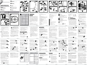
Installation
We recommend that you install the F8 in the following manner, starting with the sensor unit on the fork and working up to the
mounting bracket on the handlebar.
WHEEL MAGNET AND SENSOR INSTALLATION
STEP 1
Determine whether you will mount the computer head to the left or right of your handlebar stem. The sensor should be attached
to the fork on the same side of the bike as the computer head.
STEP 2
Using the included zip-ties, mount the sensor loosely (so that you can slide it around) to the fork blade. See Figure 3. The sensor
can be mounted at any point along the fork, but mounting the sensor slightly higher on the fork blade and running the cable up
the back side of the fork will o er better protection from rocks, branches and other snags.
STEP 3
Attach the wheel magnet loosely to one of the spokes on the same side of the wheel as the sensor. Adjust the position of the
magnet and sensor by sliding both pieces up or down to achieve 1-3mm of clearance between the two (1mm is about the
thickness of a penny). See Figure 4. If the magnet and sensor are not close enough, the computer will not pick up a reading
AUTO SLEEP
To prolong battery life, the F8 will automatically enter “sleep” mode after 10 minutes of non-use. The computer will automatically
restart as soon as it receives input from the speed sensor, or when any button is pressed.
SCAN MODE
Allows hands free viewing of all display screens. When scan mode is activated, the computer will scroll through all display screens
on a continuous loop, displaying each screen for two seconds. To activate scan mode, press and hold the LEFT button for three
seconds in any display screen. To exit scan mode, press the LEFT or RIGHT button in any display screen.
Determine Wheel Size:
The F8 uses wheel circumference (measured in millimeters) to calculate speed and distance. Before you can program the F8 you
must calculate wheel circumference using one of the three methods below.
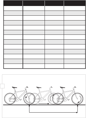
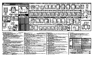
1. Select size from chart (least accurate): Use the chart below to nd the circumference for your tire size. The chart lists the
programming sizes for some of the most popular tire sizes currently in use. These numbers are estimations which may not
precisely match the circumference of your wheel, due to variations in tire size between brands and models.
2. Measure wheel diameter (more accurate): Measure your wheel diameter (including wheel and tire) in millimeters (1 inch =
25.4mm) and multiply by 3.1416. This value is your wheel circumference.
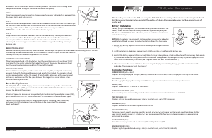
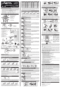
3. Perform roll-out test (most accurate): See Figure 2.
STEP 1
Stand your bicycle upright. With your tire in ated to its
proper pressure, rotate your front wheel so that the valve is
located at the bottom (6 o’clock position). Make a mark on
the oor to indicate the valve location.
STEP 2
Roll the bicycle forward in a straight line for one complete
wheel revolution, until the valve is again at the bottom
(ideally, you should be on the bike). Make a mark on the
oor to indicate the valve location.
STEP 3
Measure the distance between the marks in millimeters
(1 inch = 25.4mm). This value is your wheel circumference.
Program the Computer
Before using your F8, you must program wheel size (see
“Determine Wheel Size,” above), select a speed scale (miles
or kilometers), set the odometer (if desired) and set the
clock. The rst step is to select the speed scale.
Select Miles or Kilometers, Program
Wheel Size & Set the Odometer
The F8 is capable of displaying speed and distance
information in either miles or kilometers. Also, the
odometer can be programmed so that cumulative
mileage can be restored after a battery change or
transferred from another computer.
(SELECT MILES OR KILOMETERS)
STEP 1
Press the RIGHT button to advance to the Odometer display screen (ODO). In the Odometer display screen (ODO), press and hold
the RIGHT button for three seconds.
STEP 2
“km/h” or “m/h” will appear on the right side of the screen. Press the LEFT button to select miles (m/h) or kilometers (km/h).
16 x 1.75
20 x 1.75
26 x 0.75
24 x 1.75
24 x 1
1272
1590
1948
1907
1954
26 x 1.0
26 x 1.6
26 x 1.5
26 x 1
1973
2105
2026
2051
26 x 1.75
26 x 2
26 x 2
26 x 1.9
2070
2089
2114
2133
TIRE SIZE
CIRCUMFERENCE
1
/
8
3
/
8
3
/
8
27 x 1
28 x 1.5
28 x 1
28 x 1
28 x 1.75
2199
2224
2268
2265
2205
700 x 18c
700 x 25c
700 x 23c
700 x 20c
2102
2114
2133
2146
700 x 28c
700 x 40c
700 x 37c
700 x 32c
2149
2174
2205
2224
TIRE SIZE
CIRCUMFERENCE
3
/
8
1
/
2
1
/
4
1x
Distance in mm / inch
2

Delta i konversationen om denna produkt
Här kan du dela vad du tycker om E3 F8 Cykeldator. Om du har en fråga, läs först noggrant igenom manualen. Att begära en manual kan göras genom att använda vårt kontaktformulär.