32
GBGB
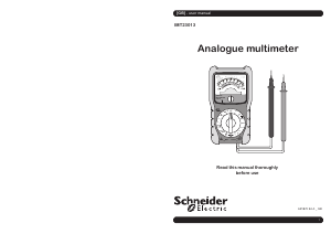
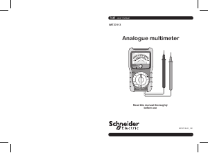
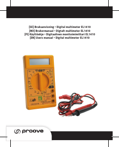
INTRODUCTION
This meter is a rectifier type, permanent-magnet moving coil instrument for measuring
DC and AC voltage, DC current, resistance, continuity, battery and decibels. It is easy to
operate and is a very useful test tool.
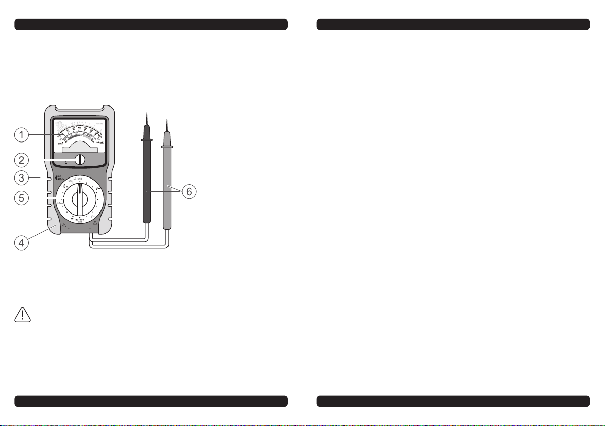
FRONT PANEL
SAFETY INFORMATION
This meter has been designed according to IEC 61010 concerning electronic measuring
instruments with a measurement category (CAT Ill 300V) and pollution degree 2.
WARNING
To avoid possible electric shock or personal injury, follow these guidelines:
• Do not use the meter if it is damaged. Before you use the meter, inspect the case.
• Inspect the test leads for damaged insulation or exposed metal. Check the test leads
for continuity. Replace damaged test leads before you use the meter.
• Do not use the meter if it operates abnormally. Protection may be impaired. When in
doubt, have the meter serviced.
• Do not operate the meter where explosive gas, vapour, or dust is present.
• Do not apply a voltage or current higher than the selected range's upper limit between
the test lead probes.
• Before use, verify the meter’s operation by measuring a known voltage.
• When measuring current, turn off power to the circuit before connecting the meter to
the circuit Remember to place the meter in series with the circuit.
• When servicing the meter, use only specified replacement parts.
• Use caution when working with voltage above 30 V AC rms, 42 V peak, or 60 V DC.
Such voltages pose a shock hazard.
• When using the probes, keep your fingers behind the finger guards on the probes.
• Connect the black test lead before you connect the red test lead. When you disconnect
test leads, disconnect the red test lead first.
• Do not operate the meter with the battery cover or portions of the case removed or
loosened.
• To avoid electric shock, do not touch any conductor with hand or skin, and do not
ground yourself.
• When an input terminal is connected to dangerous live potential, it is to be noted that
this potential can occur at all other terminals!
• Remove the test leads from the circuit under test before opening the battery cover or
the case.
• CAT Ill - Measurement Category Ill is for measurements performed in the building
installation. Examples are measurements on distribution boards, circuit breakers,
wiring, including cables, bus-bars, junction boxes, switches, socket-outlets in the fixed
installation, and equipment for industrial use and some other equipment, for example,
stationary motors with permanent connection to the fixed installation.
Do not use the meter for measurements within Measurement Categories IV.
CAUTION
To avoid possible damage to the meter or to the equipment under test, follow these
guidelines:
• Disconnect circuit power and discharge all capacitors before testing resistance and
continuity.
• Use the proper function and range for your measurements.
• Before rotating the selector switch to change functions, disconnect the test leads from
the circuit under test.
SYMBOLS
Alternating Current
Direct Current
DC or AC
Caution, risk of danger, refer to the operating manual before use.
Caution, risk of electric shock.
Earth (ground) Terminal
Fuse
Conforms to European Union directives
The equipment is protected throughout by double insulation or reinforced
insulation.
TECHNICAL DATA
Measurement Range
DC Current
Ranges: 0.6 ~ 12 ~ 600 mA
Accuracy at FSD: 5
DC Voltage
Ranges: 12 ~ 60 ~ 120 ~ 300 V
Accuracy at FSD: 5
AC Voltage
Ranges: 12 ~ 60 ~ 300 V
Accuracy at FSD: 5
Resistance
Ranges: Ω X 10 (scale center at 50 Ω)
Ω X1k (scale center at 5 kΩ)
Accuracy: 5% of arc
Battery Test
Ranges: 1.5 V (AA, AAA)
9 V
1.5 V (button cell)
Decibel
Ranges: -20 ~ +23 (~23+14 ~ 23+28 dB)
2. DC Voltage Measurement
1. Set the selector switch to the desired ‘ ‘ range.
2. Connect the test leads across the circuit to be measured.
Note: The black test lead must be connected to the negative potential of the circuit,
the red test lead must be connected to the positive potential of the circuit.
If the pointer deflects to the left of the scale, reverse the test leads.
3. Use the chart below as a guide to reading DC voltage measurements:
DCV Range Setting Read following Scale and Multiply reading by
12 0 - 12 1
60 0 - 60 1
120 0 - 12 10
300 0 - 300 1
3. AC Voltage Measurement
1. Set the selector switch to the desired ’ ‘ range.
2. Connect the test leads across the circuit to be measured.
3. If the selector switch is in AC 12 V range position, reading is taken from the third scale
( ’ 12 ‘ scale). If the selector switch is in 60 V or 300 V range position, reading is
taken from the second scale ( the ’ ‘ scale ). Use the chart below as a guide to
reading AC voltage measurements:
ACV Range Setting Read following Scale and Multiply reading by
12 0 - 12 1
60 0 - 60 1
300 0 - 300 1
4. DC Current Measurement
1. Set the selector switch to the desired ’ mA ‘ range.
2. Turn off power to the circuit to be tested. Discharge all capacitors.
3. Break the circuit path to be tested, connect the red test lead to the more positive side
of the break and the black test lead to the more negative side of the break.
4. Turn on power to the circuit.
Note: If the pointer deflects to the left of the scale, turn off the circuit power, reverse
the test leads and then turn on the circuit power.
5. Use the chart below as a guide to reading DC current measurements:
DCA Range Setting Read following Scale and Multiply reading by
0.6 0 - 60 0.01
12 0 - 12 1
600 0 - 60 10
5. Resistance Measurement
1. Set the selector switch to the desired ’ Ω ‘ range.
2. Turn the 0Ω adjuster knob until the pointer rests in the ’ 0Ω ‘ position at the right end
of the upper scale while shorting the two test leads together.
Note: If the pointer cannot be adjusted to the ’ 0 ‘ position, replace the battery
(AA, 1.5 V battery).
3. Connect the test leads across the object to be measured.
4. Reading is taken from the upper scale. To get a correct resistance value, multiply the
reading by the multiplier specified in the range selected. For example, if you use the
’ X10 ‘ range, you must multiply the reading by 10, the result is the resistance value of
the tested object.
6. Continuity Test
1. Set the selector switch to the ’ ‘ range.
2. Connect the test leads across the circuit to be tested.
3. If the resistance of the circuit is less than about 20 Ω, the built-in buzzer will sound.
Note: Because the battery’s voltage and components discreteness can affect the
resistance value at which the buzzer sounds, the buzzer may sound at a resistance
value which is different from 20 Ω. This is normal.
7. Decibel Measurement
• Decibel is measured in the same way as ACV measurement reading the dB scale
instead.
• For measurements in the ACV 12 V range, the dB scale (-20 ~ +23) is read directly. If
the reading is higher than +23 dB, use the 60 V or 300 V range, and add a fixed sum of
dB to the respective reading as follows:
- For ACV 60 V range, add 14 dB to the reading.
- For ACV 300 V range, add 28 dB to the reading.
Note: When measuring a signal which contains a direct current, a 0.1 µF blocking
capacitor with the voltage endurance of more than 300 V should be connected in
series.
8. Battery Test
1. Set the selector switch to the desired ‘ BATT. ’ range according to the rated voltage of
the battery to be tested.
Note: The ‘ BUTTON 1.5V ’ range is for testing 1.5 V button cells.
2. Connect the red test lead to the anode of the battery to be tested and the black test
lead to the cathode of the battery.
Red area of the ‘ BATT ’ scale indicates that the battery is low.
Green area of the ‘ BATT ’ scale indicates that the battery is high.
‘ ? ’ area indicates that the battery‘s condition is marginal.
REPLACING BATTERY AND FUSE
The battery is low and should be replaced if the pointer can not be set to the zero at the
right end of the top scale by the on adjuster knob while the two test leads are being
shorted together.
To replace battery, remove the holster from the meter. Then remove the screw on the
battery cover and remove the battery cover. Replace the exhausted battery with a new
one of the same type (1.5 V battery, AA or equivalent), make sure that the polarity
connections are correct. Reinstall the battery cover, the screw and the holster.
If the fuse blows because of overload, you should replace it immediately. To replace
fuse, remove the holster and the battery cover. Then remove the screws on the back cover
and remove the back cover. Replace the blown fuse with a new one of the same ratings
(630 mA / 300 V, Fast fuse). Reinstall the back cover, the battery cover and all the screws
correctly. And reinstall the holster.
NOTE
1. This manual is subject to change without notice.
2. Our company will not take the other responsibilities for any loss.
3. The content of this manual can not be used as the reason to use the meter for any
special application.
DISPOSAL OF THIS ARTICLE
Dear Customer,
If you at some point intend to dispose of this article, then please keep in mind that
many of its components consist of valuable materials, which can be recycled.
Please do not dispose of it in household waste, but check with your local council
for recycling facilities in your area.
Continuity Test
If resistance is less than about 20 Ω, the built-in buzzer will sound.
Sensitivity: 2 kΩ
/ V DC / AC
Operating Environment: Temperature: 0°C ~ 50°C
Relative Humidity: < 85%
Storage Environment: Temperature: 0°C ~ 60°C
Relative Humidity: < 85%
Size: 140 mm x 75 mm x 50 mm
Weight: About 275 g (including battery)
SCALE INSTRUCTION
There are five scales:
• The upper scale is for resistance measurements.
• The second scale (the ‘ ’ scale) is for measurements of DC voltage, AC voltage
(except ACV 12 V range), and DC current.
• The third scale (the ‘ 12 ’ scale) is only for AC voltage measurements in 12 V range.
• The fourth scale (the ‘ dB ’ scale) is for decibel measurements.
• The fifth scale (the ‘ BATT ‘ scale) is for battery test.
OPERATING INSTRUCTION
1. Points to be Observed before Operation
1. Before measurement, check the pointer to see if it is directly over the ’ 0 ‘ position of
the ’ ‘ scale (or the ’ 12 ‘ scale ), and if not, adjust the pointer with the zero
adjust control (see Figure 1).
2. If the magnitude of the voltage or current to be measured is not known beforehand,
always set the selector switch to the highest range, and then work down to an
appropriate range in order to avoid damage to the meter.
3. To avoid electric shock, do not touch any conductor with hand or skin.
60
120
300
600
BATT.
300V MAX
ANALOG
MULTIMETER
CAT III
600mA MAX
FUSED
300
12
60
12
12
1.5V
0.6
1. Pointer
2. Zero adjust control
3. 0Ω adjuster know
4. Holster
5. Selector switch
6. Black and red test lead


Delta i konversationen om denna produkt
Här kan du dela vad du tycker om Schneider IMT23013 Multimeter. Om du har en fråga, läs först noggrant igenom manualen. Att begära en manual kan göras genom att använda vårt kontaktformulär.