Symbols and notes
Installation
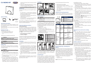
Electric connection
About these instructions
Safety notes
Intended use
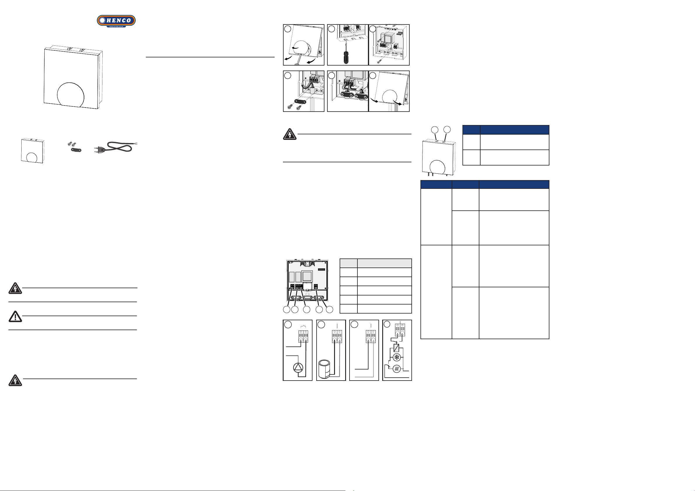
Scope of supply
Conformity
Personnel-related preconditions
Indications and operating elements
Commissioning
Pairing the room control unit to a heating
zone
Perform a radio test
Connecting (pairing) / separating base
stations
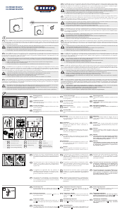
1 x
3 x 1 x*
*optional
The following symbols show
¾ that an action must be performed.
9 that a precondition must be met.
• a list
Safety notes are marked by horizontal lines:
WARNING
Electrical voltage! Danger to life!
The shown symbol warns against electrical voltage.
CAUTION
Damage of the overall system
The shown symbol warns against damage.
WARNING
Danger to life due to the electrical voltage at
the base station
¾ Always disconnect from the mains network and se-
cure against unintended activation before opening
it.
¾ Disconnect external voltages and secure against
unintended activation.
¾ Only use the product if it is in flawless state.
¾ This unit is not intended to be used by persons
(including children) with restricted physical, sen-
sory or mental skills or who lack experience or
knowledge. If necessary, these persons must be
supervised by a person responsible for their safety
These instructions are for electric equipment instal-
lers or electronic engineers and for maintenance and
cleaning personnel.
These instructions must be kept and to be handed
over to future users.
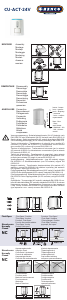
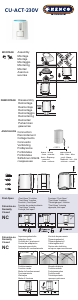
The base station Radio 230 V of the type BSF 20102-01
serves for
• the realisation of a room-by-room temperature
control system (readjustment) with a heating zone
for heating and cooling systems
• the connection of an actuator, a room control unit,
a pump and a CO signalling unit
• a fixed installation
• the extension of a room-by-room temperature
control with a base station Alpha 2 Radio
Every other use, modification and conversion is ex-
pressively forbidden and leads to dangers the manu-
facturer cannot be held liable for.
All safety notes in these instructions must be obser-
ved in order to avoid accidents with personal damage
or property damage.
Authorised specialists
The electrical installations must be performed accor-
ding to the current VDE regulations as well as accor-
ding to the regulations of your local electric power
utility company. These instructions require special
knowledge corresponding to an ocially acknowled-
ged degree in one of the following professions:
9 Electrical Equipment Installer or
9 Electronics Engineer
according to the profession designations ocially an-
nounced in the Federal Republic of Germany, as well
as according to comparable professions within the Eu-
ropean Community Law.
This product is labelled with the CE Marking and thus
is in compliance with the requirements from the gui-
delines:
9 2004/108/EG with amendments “Council Directive
on the approximation of the laws of the Member
States relating to Electromagnetic Compatibility”
9 2006/95/EG with amendments “Council for Coor-
dination of the Regulations of EU Member Coun-
tries regarding the electrical equipment for use
within certain voltage limits”
9 “Radio and Telecommunications Terminal Equip-
ment Act (FTEG) and Guideline 1999/5/EG (R&T-
TE)”
Increased protection requirements may exist for the
overall installation, the compliance of which is the re-
sponsibility of the installer.
4
5 6
31
2
The wiring of a room-by-room temperature cont-
rol system depends on several factors and must be
planned and carried through carefully by the installer.
The following preconditions must be met for the ter-
minal connections:
9 solid wire: 0.5 – 1.5 mm²
9 flexible wire: 1.0 – 1.5 mm²
9 8 - 9 mm insulation stripped o the wire
9 The wires of the actuators can be used with facto-
ry-mounted end sleeves
9 In addition to the cable fixing, a strain relief must
be provided by the customer
see electrical
connection
No. Designation
1 Pump
2 Actuator
3 Mains connection
4 Change over
5 Cable fixing
No. Designation
1 syBUS key /
Master LED (blue)
2 rmBUS key /
Heating zone LED (green)
N‘
2
L
N
N
L
N
L
3
N
L
4
If an an external change-over signal is used as shown
in 4, the overall installation switches accordingly bet-
ween heating and cooling.
2
1
The base station is operated with the two push-but-
tons with integrated LED at the top of the base station.
The base station is in installation mode during the
first 30 minutes after switching on the mains voltage.
The target and actual temperatures are compared in
this mode, all other functions are deactivated. If the
actual temperature is below the target temperature,
the output is activated at the base station. This allows
signalling at the base station without delay, enabling
the control of the allocation between the room cont-
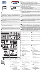
If several base stations are used in one heating system,
a maximum of seven units can be paired for the exch-
ange of global system parameters via radio. In order to
enable a stable communication between the base sta-
tions, they must be within the radio range. Communi-
cation is done according to the Master/Slave princip-
le. Requirements and status messages are exchanged
between the units. The master unit centrally controls
the directly connected functions/components.
• CO input
• Pump connection
Note: The base station the pump is connected to must
¾ Press the rmBUS button of the base station for
three seconds in order to start the pairing mode.
9 The LED “Heating zone” flashes.
9 For three minutes, the heating zone is ready to
receive the pairing signal of a room control unit.
¾ Activate the pairing function at the room control
unit (see Room Control Unit Manual).
9 The pairing mode is left after establishing a suc-
cessful allocation.
9 The LED rmBUS will light up for 1 minute.
The radio test allows to verify the communication bet-
ween the base station and a paired room control unit.
The radio test must always be carried through at the
planned installation location of the room control unit.
9 The base station is not in pairing mode for this.
¾ Start the radio test at the room control unit (see
Room Control Unit Manual).
9 The heating zone allocated to the room control
unit is activated for 1 minute and switched o or
on depending on the status of operation.
¾ If there is no activation, the reception conditions
are unfavourable. Proceed as follows:
¾ Taking into account the installation conditions
of the room control unit, change the installati-
on position until you have a reception signal,
or
¾ Use the optional accessory "Repeater" in order
to amplify the radio signal. Observe the respec-
tive manual for installation.
or receive instructions from this person on how to
use this unit.
¾ Ensure that children do not play with this device.
Children must be monitored if necessary.
¾ In case of emergency, disconnect the complete
room-by-room temperature control system.
WARNING
Danger to life due to the electrical voltage at
the base station
¾ All installation work must be performed under the
absence of voltage.
be configured as master.
The pairing of base stations is done as follows:
¾ Press the syBUS button of the base station to be
configured as master for three seconds in order to
start the pairing mode.
9 The LED “Master” flashes.
9 For three minutes, the pairing mode is ready to
receive the pairing signal of another room control
unit.
¾ Press the syBUS button of the base station to be
configured as slave two times consecutively for
one second, in order pair it with the master.
9 The paring mode ends automatically after the pro-
cess has finished.
9 The LED “Master” lights up for one minute if the
base station was configured as master.
9 The LED "Master" flashes if the base station has
been configured as slave.
The separation of paired base stations can be perfor-
med as follows:
¾ Press the syBUS button of the base station to be
separated, for three seconds in order to start the
pairing mode.
9 The LED “Master” flashes.
¾ Press the syBUS push-button again for a duration
of 10 seconds.
9 The base station restarts.
Action Display Function
Without
pressing a
key
LED
Master
Operating mode display
on: Cooling
o: Heating
LED
Heating
zone
Operating mode display:
on: Actuator activa-
ted
o: Actuator not
activated
Pressing
the syBUS
key for
approx 1
second
LED
Master
Display of base pairing
mode for 1 minute:
on: Master
flashing: Slave
o: Individual
device
LED
Heating
zone
Shows the status of the
base station for 10 se-
conds:
o: mains voltage
missing
lighted: base station rea-
dy for operation
rol unit and the output of the base station.
¾ Switch on the mains voltage.
• The LED light up for about 15 seconds.
• The base station initialises the installation mode
for 30 minutes.
• If the base station is parametrised for NC actu-
ators, all heating zones are activated for 10 minu-
tes in order to unlock the first-open function of the
NC actuators.
1
CUMONORF


Delta i konversationen om denna produkt
Här kan du dela vad du tycker om Henco CU-MONO-RF Thermostat. Om du har en fråga, läs först noggrant igenom manualen. Att begära en manual kan göras genom att använda vårt kontaktformulär.