1.2m
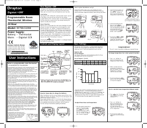
ID Feature: Description: Factory Pre-Set:
5 BACKLIGHT Available options are: On with timeout (TIMED), Always Off (OFF) TIMED
6 OFFSET Adjust displayed temperature to suit personal needs (-5 to 5°C) 0.0°C
7 LOCK Protect MiStat against unauthorised use. If active, any key press will show LOCKED for a few Secs.
To lock: Enter your 3 digit code for protection.
To unlock: Press +&- key for approx. 5 sec. Enter your 3 digit code
000
Master code 401
8 CTRL-TYPE Configure the control parameters for the specific application
9 CTRL-ALG Select TPI, TP or On/Off TPI
CYCL-RATE (only shows when CTRL-ALG is TPI
or TP)
Select 6 (GAS) cph (cycles per hour), 12 (ELECtric) cph or 3 (OIL) cph 6 cph
HYST (only shows when CTRL-ALG is On/Off) Select OFF, 0.1 to 5°C (OFF = No temperature hysteresis, even on very low temp. changes, the
relay will switch over according to MIN-OnOFF time)
0.5°C
MIN-OnOFF (only shows when CTRL-ALG is On/Off) Select 1 to 30 minutes (The minimum duration for the relay to be On or Off) 5 min
DONE To exit CTRL-TYPE sub menu
10 VALV-PROT The output will be activated for the specified time (in Minutes). This will happen weekly, related to
the last actuation of the output. Select OFF, 1 to 10 Minutes.
OFF
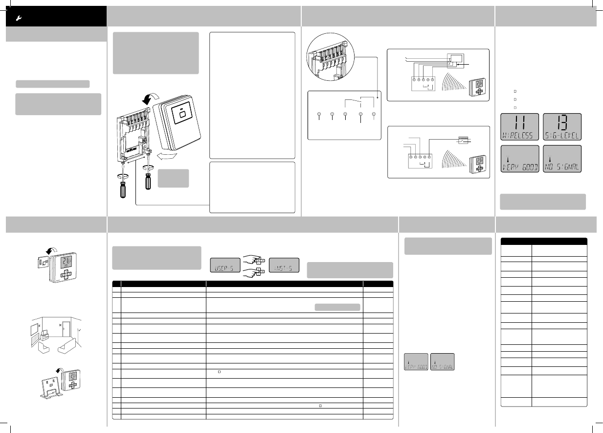
11 WIRELESS To create a radio link with the receiver or to view the RF signal quality Pre-bound
12 BIND Press (
) key to start connecting to the receiver.
NB. “binding” must also be activated on the receiver, see Step 6 Commissioning
BINDING An RF connection to the receiver will be created. If successful, the SIGNAL level will be displayed.
If unsuccessful, FAILED will be displayed.
13 SIG-LEVEL Indicates the quality of the RF transmission
VERY GOOD, GOOD, POOR, NO SIGNAL
DONE To exit WIRELESS sub menu
15 PROD-INFO View the product details, e.g. Part number, Firmware revision etc. Use (
) key to show the details
16 RESET Will reset all settings to factory pre-sets OFF
DONE Exit from the settings menu to INST-S
INSTALLATION Guide
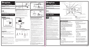
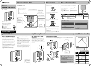
Step 3: Signal Strength
→
The MiStat Room thermostat is prebound to the
MiStat receiver in the factory so they just need
to be positioned in the best place for wireless
communication. To help with this there is a built in
Signal strength indicator, available in the Installer
settings menu on the MiStat thermostat, as shown.
It is recommended that the signal strength is Good
or Very Good to ensure ongoing communication is
maintained.
To enter signal strength menu (see step 5 for more detail))
• Press + & - for approx. 5 secs, then scroll (+/-) to show
INST-S,
• press (
) to enter the installer menu,
• Press +/- until 11 WIRELESS is shown,
• press ( ) to enter,
• press +/- to show 13 SIG-LEVEL as shown,
• press ( ) to see the current signal strength.
Step 4: Mounting Options Step 5: Installer Settings
→
Once the best position has been identified, the MiStat N
should be fixed to the wall using the wall bracket as
shown.
Customize the MiStat according to application needs.
NB. MiStat can also be positioned using the table
stand included.
Care should be taken to mount the thermostat in a
position which is not subject to direct sunlight or
draughts. Preferably it should be mounted on an inside
wall about 1.2m (4ft) above the floor in a position where
it can respond to room temperature but away from the
direct influence of radiators or other appliances giving
off heat.
MiStat
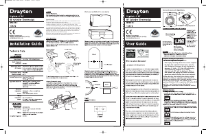
Step 1: Mounting the Wall-plate Step 2: Wiring
! IMPORTANT:
Installation must only be carried out by a
qualified electrician or heating engineer.
Make sure mains input has a 3 amp fuse.
! CAUTION! Before installation, make sure the
mains supply is switched off!
Option 2: Using an existing wall-plate
Loosen the securing screws on the old receiver
and unplug it. Check that there’s 20mm
clearance to the right of the wall-plate and 25mm
above it. Check the wiring diagram for your
product model to compare terminals and, if
necessary, change the wiring of the wall-plate to
suit. Now plug the MiStat R unit into the
wall-plate and tighten the securing screws.
Check the 3A fuse, and switch on the mains.
Option 1: Fitting a new wall-plate
The ideal location is close to the boiler or central
heating system. For the best performance install
in an open space, at least 30cm distance from any
metal objects including wall boxes and the boiler
housing. It is recommended that the MiStat R is
mounted on the wall nearest the final location of
the MiStat N room unit and not less than 30cm
from the boiler side panel.
Loosen the securing screws, remove the wallplate
and, if surface wiring is to be used, snap out
the cable entry strip on the bottom edge of the
wallplate with a pair of pliers. Fix the wallplate,
terminals at the top, either direct onto the flat
wall using wall plugs and no 6 x1” wood screws
or on a plastic flush mounting single conduit box
using M3.5 x 14 screws. Check that there’s 20mm
clearance to the right of the wall-plate and 25mm
above it. Complete the wiring to the MiStat R
wallplate in accordance with the wiring diagram
in step 2, to comply with current IEE regulations.
Place the MiStat R onto the wallplate and tighten
the securing screws.
Check the 3A fuse, and switch on the mains.
Warning: Installing the MiStat R too close to the
metal side panel or mains cables may interfere
with the radio signal.
→ →
Applications
The electronic room thermostat MiStat N can be used
for temperature control together with:
• Boilers
• Oil and gas warm water heating
• Actuators of floor heating systems or radiators
• Circulating pumps
• Heat pumps
A MiSat R receiver is required for operation.
→
Note: To ensure a properly working heating
system, the menu items in the Installer settings
have to be set according to the needs of the
heating system, see step 5.
Note: To ensure a properly working heating system,
the menu items in Installer settings have to be set
according to the needs of the heating system.
There can be gaps in the ID numbering.
! DO NOT
use a surface
mounting box
This product is double insulated and
does not require an earth connection.
The MiStat R should be wired to the
boiler or central heating wiring using the
correct type of cable or flex. The MiStat
R should be wired to replace hard wired
room or programmable thermostats,
as shown on the system or boiler wiring
diagrams.
Always check other manufacturers
instructions for compatibility.
N L 1 2 3
230V AC 50Hz
Fused 3A
Common
heating
satisfied
or call for
cooling
Call for
heat
Volt free contacts
Combi boiler basic wiring layout
Zone control basic wiring layout
Note: If not bound, the bind screen will be visible.
For commissioning see Step 6
Note: Only needed if not already bound, ie if
replacing either the MiStat thermostat or the
MiStat receiver.
To exit Installer Settings
Press +/- until ‘DONE’ is shown, then press ‘Select’ or
press + & – keys for approx. 5 seconds to exit. If there
is no key pressed for 2 Minutes, the system will exit the
menu, any changes will be saved.
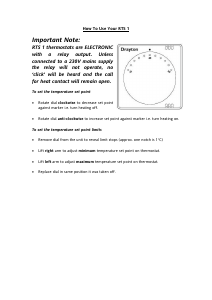
1. Turn on power for the receiver. The red lamp will
come on. (if green lamp is visible, the device is
already bound, no further action needed here)
(If a separate programmer/Timer is fitted, ensure
that it is switched on)
2. Push the button for >5 Seconds and the LED will
flash red – yellow – green --- -red – yellow - green…
3. Enter binding mode on the corresponding
MiStat room unit, see Step 5: Installer settings ,
item 11
Important: It is essential, that the binding is
carried out between the corresponding room
unit and the receiver
4. If binding is successful, the signal strength will
be indicated on both the MiStat room unit and
the MiStat receiver as follows. If unsuccessful,
FAILED will be displayed. If POOR SIGNAL
is displayed, look for a better location. If NO
SIGNAL is displayed, try connecting again with
the room unit in a different position.
MiStat Room Unit
MiStat Receiver
Immediately after binding, these signals will indicate
the signal quality for 1 minute.
• three green flashes = Very good signal
• double amber flashes = Good signal
• single red flashes = Poor signal
• steady red = No signal
To check the wireless connection
A green lamp on the receiver will indicate a good RF
connection.
→
To enter Installer Settings
Press + & – keys for approx. 5 Seconds to enter the
settings menu as shown.
Note: If not bound, the bind screen will be visible.
For commisioning see Step 6
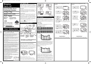
Technical Data
Step 6: Commissioning
MiStat N110R & MiStat R111M
Supply voltage MiStat N: 2 x AA 1,5V alkaline
batteries
MiStat R: 230V
Switch rating MiStat R: 2(1)A 230V a.c.
Ambient
temperature
Operating: 0°C to 45°C;
Storage: –20°C to 55°C;
Battery life MiStat N: 2 years (typically)
Temperature
range
5°C to 30°C
Temperature
resolution
0.5 °C, display and setting
Control accuracy <0.6°C at 4°/hour
Wiring Mistat R: Fixed wiring only, to comply
with current IEE regulations (BS7671)
MiStat N: No wiring required
Mounting MiStat R: Industry standard wallplate
MiStat N: Wall bracket or table stand
Radio frequency 868.3 (Bi-directional communication)
Radio signal range 30m typically. The range may be
affected by the composition / density
and number of walls between the
MiStatN and MiStatR
Pollution degree 2
Software class A
Rated impulse
voltage
MiStat R: 2.5kV
Ball pressure test
temperature
MiStat R: 75°C
Relevant EC
Directives:
2006/95/EC Low Voltage Directive
2004/108/EC Electromagnetic
Compatibility Directive
1995/5/EC R&TTE Directive
2006/66/EC Battery Directive
2011/65/EU RoHS Directive
Applied
Standards:
EN60730-1; EN60730-2-9
ETSI EN 300 220-3; ETSI EN 301 489-3
eg. eg.
eg. eg.
→
User Code:
N L 1 2 3
L
MiStat R
MiStat R
Switched live
from wiring
centre
Motorised valve
N
To boiler
and/or
pump
Radio signals
to MiStat R - no wiring
230V AC
fused 3A
N L 1 2 3
L -
N -
Radio signals
to MiStat R - no wiring
Sw
tched
230V AC
fused 3A,
Internal
boiler
electronics
External
controls
connections
N L 1 2 3
L
MiStat R
MiStat R
Switched live
from wiring
centre
Motorised valve
N
To boiler
and/or
pump
Radio signals
to MiStat R - no wiring
230V AC
fused 3A
N L 1 2 3
L -
N -
Radio signals
to MiStat R - no wiring
Sw
tched
230V AC
fused 3A,
Internal
boiler
electronics
External
controls
connections
If POOR is displayed, look for a better location.
If NO SIGNAL is displayed, try connecting again with
the room unit in a different position.
Caution!
The radio receiver may be installed only by a competent
electrician in compliance with the circuit diagram
enclosed in the top housing cover or in compliance
with these instructions. The current safety regulations
must be observed.
In order to achieve protection class II, adequate
installation measures must be taken.
This radio receiver, which can be installed separately,
is designed exclusively for temperature control in dry
and closed rooms and standard environments. This
electronic device was created according EN60730-1, it
operates according working principle 1C.
It has to be placed in a location where it will be able to
control the room temperature.
6444 Invensys MiStat N 06490191001 IssE.indd 2 27/09/2013 09:26

Delta i konversationen om denna produkt
Här kan du dela vad du tycker om Drayton MiStat N Thermostat. Om du har en fråga, läs först noggrant igenom manualen. Att begära en manual kan göras genom att använda vårt kontaktformulär.